Jastram Marine Steering Marine Controls

DHM Specifications
Input Voltage: 12 or 24 VDC
Recommended Cable: 16 AWG 2 wire, not shielded
DHM Overview
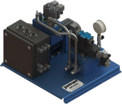
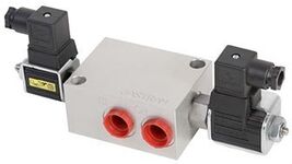
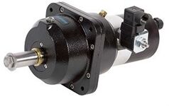
The Digital Helm Manifold (DHM) is a small, compact manifold which provides seamless transfer from fly-by-wire steering to emergency manual hydraulic steering in the event of a power failure.
- To be used in conjunction with the Jastram Digital Helm
- Within certain parameters, a single DHM can service Multiple Digital Helms
DW Specifications
Steering Wheel: The wheel is not supplied with the digital wheel.
DW shaft dimensions are: 1” by 1 7/8” shaft with a ¼” square key
Output Voltage: 12 or 24 VDC
Recommended Cable: 16 AWG 2 wire, not shielded
DW Overview
Digital Wheels are unique input devices which provide full follow-up digital electric control. The two main features of the Digital Wheel over the standard electric wheel are:
- A programmable number of wheel turns from ¼ to 10 turns lock to lock.
- When taking over control of the steering system the Digital wheel takes over at the present position of the rudder.
Under power steering, the steering wheel is turned to produce a rudder command signal. The rudder then follows up to the position requested by the wheel.
- Only compatible with Jastram Digital steering systems
- Two versions of the DW are available:
- DW-1 is the standard unit and produces one output single
- DW-2 produces two output signals – the second signals for control redundancy, or for the operation of a second steering system where independent twin steering gears are installed.
- Effort to turn the wheel does not change regardless of operating conditions
DW / FFU Overview
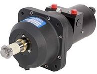
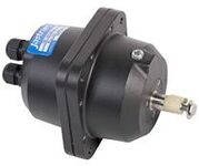
This patented hybrid hydraulic/electric unit provides full follow-up digital electric control as well as emergency manual hydraulic control. Under power steering, the steering wheel is turned producing a rudder command signal the rudder then follows up to the position requested by the wheel. In the event of a power failure, the digital helm seamlessly transfers to manual hydraulic steering. Under emergency manual hydraulic steering the numbers of turns depends on the size of the actuators.
- Under power steering mode:
- Adjustable number of wheel turns, programmable from ¼ turn to 10 turns lock to lock
- Effort to turn the wheel does not change regardless of operating conditions
- When taking over control of the steering system the Digital wheel takes over at the present position of the rudder. Other systems usually move the rudder back to center before acquiring control of the steering.
- Capable of Manual steering
- Compatible with the Jastram Digital steering system. The Digital Helm generates a digital signal to Jastram Steering Control
- To be used in conjunction with Digital Helm Manifold (DHM)
- Wheel is not supplied with the digital helm
EW 200 Specifications
Recommended Cable: 20 AWG, 3 Conductor, Standard, Copper wire
Shaft Size: Stainless steel shaft with ¾” shaft, 1:12 Taper
Voltage: 12, 24 or 36 VDC
EW 200 Overview
The EW provides full follow-up electric wheel control. When the traditional steering wheel is turned the EW produces an analog rudder command signal. The rudder will then follow-up to the position commanded by the movement of the wheel.
- Compatible with all Jastram Full Follow-up steering systems.
- Standard shaft size for customer supplied wheel
- The EW200 provides 4 turns lock to lock
- Multiple output signals are available to control a second amplifier or a rudder order indicator
- Steering wheel “feel” is adjustable
- The Internal mechanism is protected by a slip clutch to prevent damage to the unit
- Rudder Order Indicators driver boards are optional
- ROI’s are recommended so the helmsman knows where the rudder will follow-up to
- Waterproof and corrosion-resistant housing, with an IP 66 rating
HFU 360 Specifications
Power Supply : 24 VDC, 6 A
Flow Rate: 8 GPM (Max)
Working Pressure: 1500 psi (Max)
HFU 360 Overview
The HFU360 is a state-of-the-art electro-hydraulic steering system, providing full follow-up power steering with unmatched smoothness, quietness and accuracy for small to medium size vessels.
- Small, lightweight unit (18x16x13 in, 25 lbs) (457x406x330 mm, 24.9 kg)
- One or multiple helm pump stations provide FFU effortless power steering
- Optional electric controls by jog levers and/or autopilot
- True changeover to manual steering in case of electric power failure, pump set failure or cable breaks
- Hydraulic protection by double relief and load holding valves
JO100 / JO300 Specifications
Cable Requirements: 18 AWG, 3 Conductor, Standard Copper wire
Voltage: 12, 24 or 36 VDC
JO100 / JO300 Overview
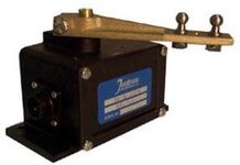
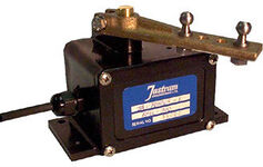
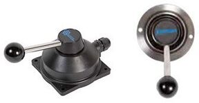
The Jastram Jog Lever provides non-follow-up (time-dependent) electric control. Jastram Jog Levers operate either completely on (as long as the switch is activated) or completely off (when it is released).
- Compatible with all Jastram’s electro-hydraulic steering systems and most third-party autopilots
- Four versions available:
- JO100-1 contains one set of microswitches
- JO100-2 contains two sets of microswitches
- JO300-1 yacht styling with one set of microswitches
- JO300-2 yacht styling with two sets of microswitches
- The spring-loaded jog switch returns to center when released (The rudder remains where positioned when the lever is released)
- Waterproof and corrosion resistant housings, with an IP 66 rating
- Supplied with 5ft (1.5m) of cable
LC100 / LC300 Specifications
Cable Requirments: 18 AWG, 3 Conductor, Standard copper wire
Voltage: 12 , 24 or 36 VDC
LC100 / LC300 Overview
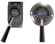
The Jastram Lever Controller provides full follow-up (way dependent) electric control.
When the steering lever is moved to the desired rudder angle, the rudder will follow-up to the position requested b the lever.
- Smoother and more accurate steering than jog steering
- Compatible with all Jastram Full Follow-up steering systems and most third-party autopilots
- The rudder position is displayed by an indicator strip below the lever arm of the LC.
- Four versions are available:
- LC100-1 produces one output signal
- LC100-2 produces two output signals - the second signal controls a second amplifier or an alarm circuit.
- LC300-1 yacht styling; produces one output signal
- LC300-2 yacht styling; produces two output signals - the second signal controls a second amplifier or an alarm circuit.
- Waterproof and corrosion-resistant housings, with an IP 66 rating
- Supplied with 5ft (1.5m) of cable
RAI 3300 Overview
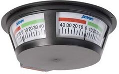
The Largest of the Indicators is the 3300 overhead three faced panoramic indicator. These are stand-alone systems comprised of three main components:
- A three faced panoramic Rudder Angle Indicator (RAI 3300)
- RAI 3300 power Supply
- Rudder Feedback Unit
- Built in dimmer allows for adjustment of the backlight
- Deckhead mounted at any convenient location in the wheelhouse
- Two Power Supply options are available:
- Input voltage of 12-24 VDC and outputs 24 VDC
- Input voltage of 100-40 VAC and outputs 24 VDC
- Cable requirements 16 AWG, 3 wire, shielded
RAI/ROI X80 Specifications
Power Supply: 24 VDC Max 180mA
Recommended Cable: 18 AWG 4 wire, shielded
RAI/ROI X80 Overview
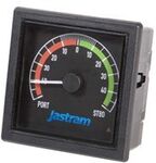
The X80 Series Rudder Angle Indicators are produced to fill the requests of Vessel operators and to meet Classification Societies requirements. The X80 Indicators come in 3 sizes to fit all bridge applications. Up to five indicators can be used with a mixture of forward and reverse scale meters.
- Wheelmark and MED Approved
- Designed to be flush-mounted for panel or console
- X80 series are rated for IP52 Protection
RFU 2000 Overview
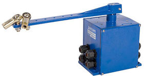
The RFU 2000 is built with cast aluminum and stainless steel and designed for heavy duty use in both commercial and pleasure crafts. Two types of devices are available for the RFU 2000 to generate the feedback signal: the standard is the potentiometer type, and second would be the optional contact free Hall Effect. All electronic circuitry necessary to develop rudder feedback signal and rudder angle signal is contained within the RFU 2000. The RFU 2000 outputs both a rudder angle indicator signal and rudder feedback signal, as well as an optional second independent second rudder angle indicator signal.
- Built in set of adjustable limit switches (an optional second set of limit switches is available).
- Unit operates on any voltage between 10-32 VDC
- Waterproof design with unique double sealed shaft and waterproof quick connect cable plugs
RFU 300 Overview
The RFU 300 is built to resist water and damage caused by vibrations from rough seas and mechanical systems. The RFU 300 features a high quality, long life potentiometer with heavy duty gears. Designed to be used only with the RAI Panoramic 3300 and RAI 301/RAI 300
- Up to three indicators can operate at the same time
- Unit operates on any voltage between 10-32 VDC
- Comes with 50’ cable
RFU 400 Overview
The RFU 400 is built to resist water and damage caused by vibrations from rough seas and mechanical systems. The RFU 400 features a high quality potentiometer with heavy duty gears, and a built in electronic driver board. The addition of the driver board in the unit eliminates the need for a 301 Indicator Designed to be used with the RAI 300.
- Up to five indicators can operate at the same time
- Unit operates on any voltage between 10-32 VDC
- Waterproof design with unique double sealed shaft and waterproof quick connect cable plugs