
Industrial Reduction Gearboxes: Selection and Application Support
At a Glance
- A reduction gearbox lowers engine or motor speed and increases output torque.
- Output speed equals input speed divided by the reduction ratio.
- Selection depends on torque, duty cycle, mounting, and engagement needs.
Diesel engines and electric motors rarely run at the speed the equipment they power needs. An industrial reduction gearbox closes that gap by converting high input speed into the lower speed and higher torque that pumps, fans, mixers, and conveyors require. This guide explains how reduction gearboxes work, where they are used, the main options available, and what to consider when selecting one.
What Is a Reduction Gearbox?
A reduction gearbox, also called a speed reducer or gear reducer, reduces the rotational speed between a power source and the equipment it drives. As speed goes down, available torque goes up, minus a small amount lost to friction in the gears and bearings. This trade of speed for torque is what allows a fast-turning engine or motor to drive slower, heavier loads efficiently.
How Reduction Ratio Affects Speed and Torque
The reduction ratio describes how many turns of the input shaft it takes to turn the output shaft once. To find output speed, divide input speed by the ratio. A diesel engine running at 1,800 RPM through a 3:1 reduction gearbox produces an output speed of 600 RPM.
Output torque moves in the opposite direction. In simple terms, output torque is approximately the input torque multiplied by the ratio, then reduced by the gearbox efficiency. A 3:1 gearbox can deliver close to three times the input torque at one third of the speed, less drivetrain losses. Because torque rises with the ratio, the gearbox, shafts, and couplings must all be rated for the higher output torque, not just the input horsepower.
Industries and Applications That Use Reduction Gearboxes
Reduction gearboxes are used anywhere engine or motor speed needs to be matched to driven equipment. Common industries and applications include:
- Agriculture: Irrigation pumps, feed mixers, and crop processing equipment
- Oil and gas: Fluid transfer pumps, drilling equipment, and mixing systems
- Construction: Dewatering pumps, concrete mixers, and material handling equipment
- Industrial pumping: Water transfer, slurry handling, and process pumping systems
- Mining and aggregates: Slurry pumps, conveyors, and mineral processing equipment
- Water and wastewater: Treatment plant pumps, mixers, and aeration equipment
- Manufacturing and processing: Conveyors, industrial mixers, fans, and blowers
Each application has its own speed, torque, and duty requirements, which is why there is no single gearbox that fits every job.
Types of Industrial Reduction Gearboxes
Several categories of gearboxes are commonly used for speed reduction behind diesel engines and electric motors. Each has strengths depending on the application.
Dedicated Reduction Gearboxes
Purpose-built reduction gearboxes are designed specifically to lower speed and increase torque for driven equipment. The Twin Disc RM series is one example, with models from the RM20 through the RM150 used on water pumps, slurry pumps, fans, blowers, and mixers. Units like these are typically offered in multiple ratios and connection styles, and with output rotation either matching the engine (engine rotation) or opposite it (anti-engine rotation).
Single-Pad Pump Drives
Pump drives are usually associated with hydraulic systems, but single-pad pump drives can also work as speed reducers in the right application. Manufacturers such as Durst, Twin Disc, and Funk offer pump drives in a range of ratios. Whether one is a practical fit depends on the required ratio, torque capacity, output connection, and mounting arrangement.
Marine Transmissions in Industrial Service
Marine transmissions have been used for decades as reduction gearboxes in industrial equipment. Units such as Twin Disc marine transmissions combine a range of sizes and ratios with integrated clutch engagement, which makes them useful when the driven load needs to be engaged and disengaged while the engine runs.
Custom Reduction Gearboxes
Some applications fall outside standard catalog products because of unusual torque, ratio, mounting, or packaging requirements. Specialty manufacturers such as Katsa, Cotta, and NAMCO build custom gearbox configurations for these cases. Custom designs generally involve longer lead times and are most common in OEM programs or demanding installations.
Mounting Options: Direct-Mount vs. Remote-Mount
A direct-mount gearbox bolts to the engine flywheel housing, creating a compact, aligned assembly. A remote-mount gearbox sits separately and connects to the power source through a driveshaft or coupling. Direct mounting saves space and simplifies alignment, while remote mounting offers more flexibility in equipment layout and can isolate the gearbox from engine vibration.
Clutch and Engagement Options
Some drives are continuously connected, meaning the driven equipment turns whenever the engine runs. Others use a clutch so the load can be engaged and disengaged. Clutch packages may be manually operated or remotely actuated, and with compatible clutch and control arrangements, push-button engagement is possible. Engagement needs should be defined early because they affect gearbox choice, controls, and cost.
How to Select the Right Reduction Gearbox
Gearbox selection involves more than horsepower and ratio. Key factors to evaluate include:
- Power source: Diesel engine or electric motor specifications, including input speed and torque
- Output requirements: Target output RPM, output torque, and direction of rotation
- Duty cycle: Hours of operation, startup loads, shock loads, and operating environment
- Physical fit: Mounting dimensions, shaft connections, and available installation space
- Supporting systems: Clutch engagement, cooling, lubrication, and torsional compatibility between the engine, gearbox, and driven equipment
Duty cycle deserves extra attention. Gearboxes are often selected with a service factor, a margin above the calculated load that accounts for shock, frequent starts, and continuous operation. A gearbox that is adequate for intermittent use may wear quickly in a 24/7 application.
Commercial factors matter too. Price, lead time, and production quantity can point toward a standard catalog unit for a single replacement or toward an engineered solution for an ongoing OEM program.
Summary
Industrial reduction gearboxes match the speed of a diesel engine or electric motor to the needs of driven equipment while multiplying available torque. The main options include dedicated reduction gearboxes, single-pad pump drives, marine transmissions used in industrial service, and custom designs. The right choice depends on input and output speed, torque, duty cycle, mounting arrangement, and whether the load needs clutch engagement.
Frequently Asked Questions
Nothing. Speed reducer, gear reducer, and reduction gearbox all describe the same device.
Divide input speed by the ratio. 1,800 RPM through a 3:1 gearbox gives 600 RPM.
Yes. Output torque is roughly input torque multiplied by the ratio, minus losses to gearbox efficiency.
In the right application, yes, depending on ratio, torque capacity, needed rotation, and mounting requirements.
It’s a safety margin above the calculated load that accounts for shock loads, frequent starts, and continuous duty.
Industrial Gearboxes
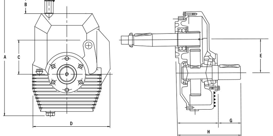
Industrial gearboxes transfer engine or motor power, reducing speed and increasing torque to drive pumps and other industrial equipment.
Resources Home